

How to Mount a Motor Properly

Mounting a motor correctly is not just a matter of tightening bolts. A poor base, soft foot, or slight misalignment can create vibration, noise, and premature bearing wear. This guide explains how to Mount Motor assemblies with care, from preparing the foundation to checking the final alignment. Small errors matter.

Motor reliability specialist Dr. Howard W. Penrose has written extensively about motor maintenance and failure prevention. A practical principle that reflects this work is: “A motor depends on its foundation, alignment, and installation checks.” Treat that as a reminder, not a substitute for the motor maker’s instructions. Every installation differs. Frame size, load, coupling, and operating conditions all affect the mounting method.

Start with the base. Check that it is clean, rigid, and free of burrs. Place the motor without forcing its feet into position. Use shims to correct uneven contact, then tighten fasteners gradually and evenly. Check shaft alignment with suitable measuring tools. A straightedge can reveal obvious errors, but precision equipment gives a more dependable result. Then verify. Turn the shaft by hand where safe and permitted, inspect the coupling, and confirm that guards and electrical connections are handled by qualified personnel. One detail is easy to miss: tightening bolts can change alignment. Recheck it after tightening. The process may feel repetitive. That is useful; careful verification is cheaper than guessing.
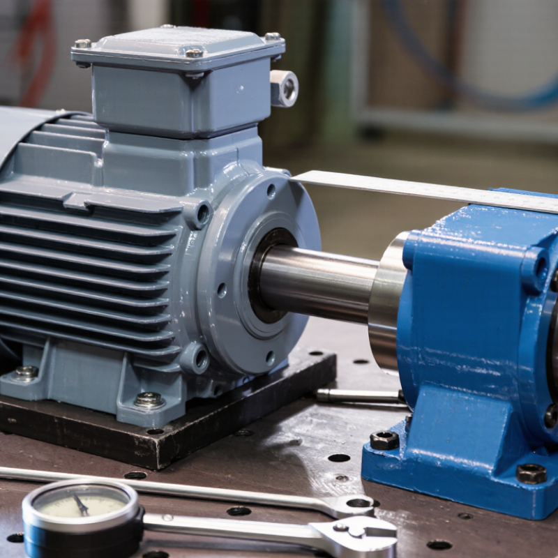
How to Mount a Motor Properly

Identify the Motor Type, Load, and Mounting Requirements

How to Mount a Motor Properly

Identify the motor type, load, and mounting requirements before drilling holes. A foot-mounted motor needs a flat, rigid base; a flange-mounted unit needs a matching face and bolt pattern. Vertical installations may require bearings designed for axial loads. Check the manual for orientation, allowable forces, and enclosure clearances. A level base can still be wrong if the driven load pulls the shaft out of alignment.

Load matters. A pump, fan, and conveyor impose different starting torque, radial force, and vibration demands. The U.S. Department of Energy’s 2014 Improving Motor and Drive System Performance sourcebook estimates motor-driven systems use about 68% of U.S. manufacturing electricity. That figure is a reminder: poor alignment or a flexible base can waste energy and shorten service life. It is easy to focus on bolt size and overlook the machine’s actual load.

Tips: Confirm the motor’s nameplate, mounting code, and load details. Use shims to correct soft feet, tighten bolts evenly, and check shaft alignment after securing the motor. A dial indicator helps reveal small offsets. Recheck vibration after startup; the first reading may not tell the whole story. I would not assume a quiet motor is correctly mounted.

Select a Compatible Mounting Base and Hardware

Choosing a compatible mounting base starts with the motor’s frame dimensions and foot pattern. Measure the distance between mounting holes, then compare it with the base slots or holes. A few millimeters of mismatch can pull the feet out of alignment. Small errors matter.

The base must support the motor’s weight and resist operating vibration. A thin, flexible plate may seem adequate on a workbench, but it can shift under repeated load. Check the base material, thickness, and attachment points against the motor documentation and expected operating conditions. Keep the mounting surface flat; use suitable shims if needed, rather than forcing a foot down with a bolt.

Select bolts that match the motor’s thread size and provide the engagement specified by its manufacturer. The bolt length should secure the motor without bottoming out in a blind hole. Use washers or locking hardware only when appropriate for the design, and tighten fasteners to the stated torque. More force is not safer. It is easy to focus on hole spacing and overlook access for a wrench or future maintenance. Check clearance around the motor before drilling, and recheck alignment after tightening.

How to Mount a Motor Properly: Select a Compatible Mounting Base and Hardware

Approximate tightening torque for common coarse-thread metric bolts, property class 8.8.

Use these values as a general reference for clean, dry steel fasteners—not as a substitute for the motor or fastener manufacturer’s specifications. Confirm that the base hole pattern matches the motor, and verify bolt grade, thread engagement, and torque requirements before installation.

Prepare the Motor and Mounting Surface

Prepare the motor and mounting surface before alignment; small defects can turn into noise, heat, or loose fasteners. The U.S. Department of Energy’s 2014 report, Improving Motor and Drive System Performance: A Sourcebook for Industry, estimates that motor-driven systems use about 68% of U.S. industrial electricity. That makes careful installation more than housekeeping. Start with a clean, dry mounting pad. Remove paint flakes, burrs, oil, and old gasket material, then check the surface with a straightedge and feeler gauges. A pad can look flat and still rock under the motor foot. Don’t trust appearance alone.

Inspect the motor feet and base for cracks, distorted holes, and raised edges. Clean the bolt holes, then position the motor without forcing it into place. Use solid, clean shims; avoid tall, uneven stacks that may shift as bolts tighten. Check the mounting plane and shaft alignment against the motor manufacturer’s tolerances, since acceptable values vary by frame and application. Tighten fasteners gradually in a cross-pattern, then recheck alignment. A torque wrench helps, but it cannot correct a poor base. Record the readings and shim locations. That step feels fussy, and it is easy to skip; later, it can save a second teardown.

Position, Align, and Secure the Motor

How to Mount a Motor Properly

Position the motor on a clean, rigid base, close to its driven equipment, with room for cooling air and maintenance access. Check the mounting surface for burrs, paint buildup, and uneven contact. A thin feeler gauge can reveal gaps beneath the feet; correct these before tightening, or the housing may distort. Keep the shaft line level where the equipment design requires it. Leave enough space to reach bolts and inspect the coupling later.

Alignment matters. Use a straightedge for a preliminary check, then a dial indicator or laser tool to measure angular and parallel offset. Follow the equipment maker’s tolerances; there is no single acceptable figure for every motor and coupling. The U.S. Department of Energy’s 2014 sourcebook, Improving Motor and Drive System Performance, estimates that motor-driven systems use about 68% of U.S. manufacturing electricity. That figure makes careful installation worth attention, though it does not quantify savings from alignment alone. Tighten anchor bolts gradually in a cross-pattern, recheck alignment, and secure the coupling only after readings are stable. A quiet first run proves little. I would still check vibration and temperature after the motor reaches operating speed; small shifts can appear under load.

How to Mount a Motor Properly - Position, Align, and Secure the Motor

Mounting step What to check Practical guidance Why it matters
Prepare the foundation Clean, rigid mounting surface; sound grout or structural support where applicable. Remove dirt, burrs, and loose material. Confirm the foundation and base are suitable for the motor’s weight and operating loads. A weak or uneven foundation can cause movement, vibration, and alignment changes.
Position the motor Shaft orientation, access for maintenance, ventilation, and cable entry. Place the motor so the shaft and driven equipment can be aligned, and keep cooling-air passages clear. Follow the motor’s installation instructions for permitted mounting positions and clearances. Correct positioning supports cooling, safe access, and reliable coupling or belt installation.
Check soft foot Whether all motor feet sit evenly on the base before final tightening. Check each foot with a feeler gauge while loosening and retightening one hold-down bolt at a time. Correct gaps with clean, full-foot shims; use the equipment or site’s specified acceptance limit. Soft foot can distort the motor frame when bolts are tightened and upset shaft alignment.
Align the shafts Parallel offset and angular misalignment at the coupling. Use a dial indicator or laser alignment tool. Adjust motor position horizontally and with shims vertically. Meet the coupling or driven-equipment manufacturer’s tolerance, accounting for operating temperature where required. Misalignment increases bearing and coupling loads and can lead to vibration, heat, or premature failure.
Secure the motor Correct bolts, washers, threads, and tightening sequence. Use fasteners of the specified size and grade. Tighten evenly to the equipment or engineering specification; do not apply a universal torque value. Even, specified clamping force helps prevent movement without damaging threads or motor feet.
Recheck after tightening Shaft alignment and foot contact after all hold-down bolts are tightened. Repeat the alignment measurements after tightening. If adjustment is needed, loosen, reposition or shim, retighten, and measure again. Tightening can shift the motor or introduce frame distortion.
Inspect before startup Coupling guard, electrical connections, grounding, rotation direction, and clearances. Follow site lockout and electrical-safety procedures. Install guards before operation and verify that the motor and driven equipment are ready for a controlled test run. A final safety and readiness check helps prevent contact hazards and damage during startup.
Monitor during operation Unusual vibration, noise, temperature, or movement. Run the equipment under the approved procedure and compare observations with established site limits. Stop and investigate abnormal conditions. Operating checks can reveal problems that were not apparent during static installation.

Always follow the motor, coupling, driven-equipment, and site-specific installation requirements when they differ from this general checklist.

Connect the Motor and Verify Its Operation

With the motor securely mounted, check the wiring diagram before connecting any conductors. Keep the power isolated while working, and have a qualified person make electrical connections when required. Confirm that the supply matches the motor’s nameplate, the ground is connected, and cables cannot rub against the shaft or frame. A tidy cable route can still conceal a loose terminal, so inspect each connection carefully.

Tips: Tighten terminals to the specified torque. Keep guards in place. Never guess at wire colors or terminal positions.

Before running the motor, turn the shaft by hand if the equipment design permits. Check for rubbing, binding, or unexpected resistance. Then restore power and test the motor briefly, standing clear of moving parts. Listen for unusual scraping or humming, and watch for excess vibration or movement at the mounting feet. Verify rotation direction against the equipment requirements; disconnect power before correcting it. Stop immediately if anything looks or sounds wrong. Compare measured current with the nameplate value using suitable equipment, and recheck mounting fasteners after the initial run. Small checks matter. A motor that runs is not automatically a motor that is operating correctly.

Article Source: