

Choosing a Turning Tool Holder is not a minor purchasing decision. It affects tool stability, cutting accuracy, setup time, and the finish left on a workpiece. In a busy machine shop, even a small mismatch between the holder, insert, and machine turret can cause vibration or delay a job. Details matter.
This guide introduces ten manufacturers with established roles in the global machining market. It considers practical factors such as holder styles, clamping systems, material options, product documentation, and access to technical support. These details help buyers compare products for turning operations, from routine production to demanding precision work. A well-known name alone is not enough. Compatibility and service matter too.
Manufacturer strengths vary by region and application. Some offer broad catalogs, while others focus on specialized tooling or particular machining needs. Product availability can also differ between markets, so a catalog page may not tell the whole story. No list is perfect. Rankings can oversimplify real purchasing decisions, and the best choice depends on the machine, material, insert, and workflow. Use this overview as a starting point, then confirm specifications with the manufacturer or an authorized supplier before choosing a holder.
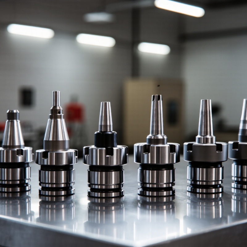
What Turning Tool Holders Are and How They Function
A turning tool holder is the rigid link between a lathe’s tool station and its cutting edge. It clamps an insert or, in some setups, a solid cutting tool. The holder keeps the edge positioned against the rotating workpiece while transmitting cutting forces back to the machine. Its shape and size must match the tool station, workpiece access, and cutting direction. Small details matter.
During a cut, the insert removes material as the workpiece spins. The holder supports the insert and helps resist vibration, heat, and pressure. A long overhang can allow the tool to flex, leaving a rough surface or uneven dimensions. Secure clamping matters, too: loose screws or debris beneath an insert can shift the cutting edge. A holder may appear sturdy, yet still be poorly suited to a particular setup. Not always obvious.
Tips: Check the holder and insert for chips or damage before installation. Keep the overhang as short as the job allows, and tighten fasteners to the tool maker’s specified torque. If chatter persists, review setup stiffness and cutting conditions; changing the holder alone may not solve it.
A practical guide to ten common turning tool holder configurations, their functions, and typical applications.
| No. | Holder Type | Typical Tooling | How It Functions | Common Applications | Key Selection Considerations |
|---|---|---|---|---|---|
| 1 | External turning holder | Indexable carbide insert | Clamps an insert at a set orientation so its cutting edge removes material from the outside diameter of a rotating workpiece. | Straight turning, shoulder turning, and general outside-diameter machining. | Match the holder geometry and insert shape to the workpiece, cutting direction, required access, and machining load. |
| 2 | Roughing holder | Robust indexable insert, often with a chipbreaker | Supports the cutting edge for higher material-removal rates and helps direct chips away from the cutting zone. | Removing stock before finishing, including machining forged or cast surfaces. | Check machine rigidity, workholding stability, insert strength, and the recommended feed and depth of cut. |
| 3 | Finishing holder | Sharp-edged insert suited to the specified finish | Positions the cutting edge for controlled, lighter cuts that can produce a more consistent surface finish. | Final passes on outside diameters, shoulders, and other accessible surfaces. | Consider insert nose radius, edge preparation, workpiece material, and the surface-finish requirement. |
| 4 | Facing holder | Indexable turning insert | Holds the insert in an orientation that allows the tool to cut across the end face, usually moving between the outer diameter and the center. | Squaring workpiece ends and machining flat faces on a lathe. | Confirm the tool can reach the required face and center area without interference; cutting direction depends on holder orientation. |
| 5 | Profiling holder | Profile or general-purpose indexable insert | Provides clearance and access for following a contour while the tool moves along a programmed or manually controlled path. | Contours, radii, tapers, and shaped external features. | Check insert clearance, tool approach, contour accessibility, and the risk of the holder contacting the workpiece. |
| 6 | Boring bar holder | Small indexable insert mounted on a boring bar | Supports a cutting edge inside a pre-existing hole to enlarge it or improve its diameter, alignment, or finish. | Internal turning, hole enlargement, and internal shoulder machining. | Choose the largest practical bar diameter and shortest practical overhang to reduce deflection and vibration. |
| 7 | Grooving holder | Narrow grooving insert | Guides a narrow cutting edge radially or axially into the workpiece to create a groove of a specified width and depth. | External or internal grooves, relief grooves, and, with suitable tooling, face grooves. | Match insert width and holder clearance to the groove dimensions, material, chip evacuation, and cutting direction. |
| 8 | Parting-off holder | Parting insert or replaceable cutting blade | Feeds a narrow cutting edge into the rotating workpiece until the component is separated from the remaining stock. | Cutting bar stock to length and separating completed parts on a lathe. | Use a rigid setup, minimize tool overhang, and verify blade alignment and clearance to help prevent deflection or pinching. |
| 9 | Threading holder | Single-point threading insert | Holds a thread-form insert while the tool advances in synchronization with spindle rotation to generate a helical thread. | External or internal threads, depending on the holder and insert configuration. | Match the insert profile and pitch range to the thread standard, and set the tool height and orientation correctly. |
| 10 | Modular tool holder | Interchangeable cutting head or attachment | Connects a replaceable cutting unit to a reusable shank or interface, allowing tools to be changed without replacing the whole assembly. | Production setups that require frequent tool changes or several turning operations. | Confirm interface compatibility, clamping security, repeatability, and adequate rigidity for the intended operation. |
Compatibility, insert designation, cutting parameters, and available configurations vary by tool system and machine setup. Consult the relevant technical documentation before machining.
