What Is a Machine Tool and How Does It Work?
A Machine Tool is more than a powered piece of workshop equipment. It is a controlled system that shapes metal, plastics, or other materials with measured force. Lathes rotate workpieces. Milling machines guide cutters across surfaces. Drilling machines create accurate holes. Modern machining centers combine several operations under computer control.
Joseph Whitworth, a respected nineteenth-century machine-tool engineer, stated, “The perfection of the machine tool is the foundation of all manufacturing.” His words still reflect industrial reality. A small error in alignment can become a large error in an aircraft bracket, engine component, or medical device. Precision begins with the machine’s frame, spindle, guides, drive system, and control software.
The working process is practical. An operator or engineer studies the drawing, selects a cutting tool, fixes the workpiece, and sets operating parameters. These include speed, feed rate, and cutting depth. Coolant may reduce heat and extend tool life. Sensors can monitor vibration, position, and temperature during production.
The machine removes material gradually.
That detail matters.
A reliable Machine Tool does not simply cut quickly. It must repeat the same movement across hundreds or thousands of parts. In my view, this is where many simple explanations become incomplete. Accuracy depends on maintenance, operator judgment, material behavior, and environmental conditions. Even a sophisticated CNC machine can produce poor results when its tools are worn or its calibration is neglected. Understanding these limits helps readers judge how Machine Tool technology really works.
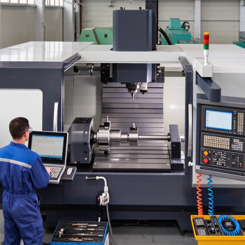
Defining a Machine Tool and Its Role in Manufacturing
What Is a Machine Tool and How Does It Work?
Defining a Machine Tool and Its Role in Manufacturing
A machine tool is a powered machine that shapes solid material with controlled motion. It may cut, drill, grind, turn, or form metal and other rigid materials. Unlike a general-purpose power tool, it supports accurate production through a fixed structure, guided movement, and secure workholding. Common examples include lathes, milling machines, grinders, and drilling machines.
Its role in manufacturing is to create repeatable parts from engineering drawings or digital instructions. A workpiece sits in a fixture or chuck, while a cutting tool removes material at a planned speed and depth. The spindle, table, and feed system must move together with little unwanted vibration. Even a small alignment error can affect a hole, edge, or bearing surface. Small errors grow.
In a real workshop, successful machining depends on more than the machine itself. Operators check tool wear, material condition, coolant flow, and finished dimensions. Measuring tools reveal problems that may not be visible during cutting. Modern control systems improve consistency, but they cannot replace sound setup decisions. The definition of a machine tool is also not perfectly fixed; advanced equipment may combine cutting, inspection, and automated handling. That overlap can make classification less clear, yet its manufacturing purpose remains practical: turning raw stock into precise, usable components.
Main Types of Machine Tools and Their Distinctive Functions
A machine tool is a powered machine that shapes solid material with controlled movement. It removes material, forms surfaces, or improves accuracy. In practical workshops, the machine, cutting tool, workpiece, and operator must work as one system.
A lathe rotates the workpiece while a cutting tool moves against it. It is suitable for shafts, threaded parts, tapers, and cylindrical surfaces. A milling machine holds the cutter on a rotating spindle. The table moves the workpiece across the cutter, creating slots, pockets, and flat faces. A drill press produces accurate holes with a vertically moving drill. It is useful for repeated drilling, although poor clamping can still cause wandering or oversized holes.
A grinding machine uses an abrasive wheel instead of a traditional cutting edge. It can produce fine finishes and tight dimensions, especially on hardened materials. A CNC machine follows programmed movements and repeats complex cuts with strong consistency. However, programming does not remove the need for judgment. Incorrect tool offsets, loose fixtures, or excessive cutting speed can damage both part and equipment. I have found that setup checks often matter more than impressive machine specifications. Small errors become obvious under a measuring gauge.
Cutting fluid may reduce heat and extend tool life, but it must match the material and process. Operators should inspect guards, secure the workpiece, and verify dimensions during production. No setup is perfect. Mistakes still teach.
Essential Components That Enable Machine Tool Operation
A machine tool is a powered system that shapes metal, wood, or other materials with controlled movement. Its essential components work together like a coordinated workshop team. The frame supports the machine and reduces vibration. The spindle or cutting head holds and rotates the tool. Motors provide force, while guideways direct movement along precise axes. Without a rigid structure, even a sharp cutter can produce rough surfaces.
The control system converts programmed instructions into physical motion. Sensors monitor position, speed, and temperature during operation. A workholding device keeps the material stable against cutting forces. Coolant may reduce heat, friction, and tool wear, although it cannot correct poor alignment. In practical inspections, loose fasteners often cause unexpected accuracy problems. A machine can appear powerful, yet small movement can spoil an entire part. That detail is easy to underestimate.
Tips: Check alignment before cutting. Keep guideways clean and lightly lubricated. Listen for unusual vibration. Measure the finished part, not only the machine display. Operators should also review tool condition and clamping pressure. This routine feels slow at first. It prevents expensive mistakes. Even experienced technicians can miss a worn bearing or a dull edge, so careful observation remains essential.
How a Machine Tool Converts Instructions Into Precise Work
What Is a Machine Tool and How Does It Work?
How a Machine Tool Converts Instructions Into Precise Work
A machine tool turns digital instructions into controlled physical movement. The process begins with a drawing, measurements, and a selected cutting strategy. Software converts this information into machine-readable commands, often containing coordinates, feed rates, and spindle speeds. The controller reads each command and sends signals to motors, which move the table, tool, or workpiece along specific axes.
Small details matter. A tool may travel 0.01 millimeters at a time. Encoders report its position, while the controller compares movement with the programmed path. If the tool cuts steel, the spindle rotates at a carefully chosen speed. Coolant may reduce heat and carry chips away from the cutting zone. A rigid fixture holds the material firmly, because even slight vibration can leave visible marks.
Precision is built through repeated checks. Operators set work offsets, measure tools, and inspect the first finished part with gauges or a coordinate measuring system. Experience still matters here. A perfect program cannot correct a loose fixture or a worn cutting edge. Mistakes happen. Sometimes, a calculated feed rate produces chatter instead of a clean surface. That result deserves investigation, not excuses. Temperature, tool wear, material hardness, and measurement technique can all change the final dimension. The machine follows instructions, but people must judge whether those instructions remain suitable.
What Is a Machine Tool and How Does It Work?
A machine tool converts programmed instructions into controlled axis movements. This chart shows the commanded X and Y positions for one circular interpolation cycle with a 25 mm radius, expressed in millimeters.
The controller calculates each coordinate from the programmed toolpath, while motors and feedback systems move the cutting tool through these precise positions.
Factors Affecting Machine Tool Accuracy, Safety, and Efficiency
A machine tool shapes metal, plastic, or other materials through controlled cutting, drilling, grinding, or forming. Its accuracy depends on rigid construction, stable fixturing, calibrated measuring devices, and correct tool alignment. Temperature also matters. Heat can expand the spindle, workpiece, or table and shift dimensions by a few microns. Tool wear creates another quiet error. A component may look correct while its edges slowly drift out of tolerance.
Safety and efficiency are closely connected. Guards must remain closed, chips should be cleared with proper tools, and operators need clear access to emergency controls. Loose clothing, poor lighting, and rushed setups create avoidable risks. Efficient machining requires suitable cutting speeds, reliable coolant flow, planned tool changes, and regular maintenance. However, faster is not always better. Excessive speed can increase heat, vibration, and tool failure.
Tips:
Check workholding before every cycle. Measure the first piece and record the result. Watch for unusual vibration or rising spindle temperature. Keep walkways dry and uncluttered. A clean machine is easier to inspect. Do not trust a familiar setup blindly; materials and tools can behave differently each day. Even experienced teams miss small changes sometimes, so periodic verification remains necessary.


