

A hydraulic connection can look simple: two steel halves, a sleeve, and a seal. Yet a poor match can cause leaks, pressure loss, contamination, or difficult maintenance. For global buyers, choosing a Hydraulic Coupler means comparing more than thread size. Pressure rating, flow capacity, connection method, materials, seal compatibility, and operating conditions all matter.
Fluid-power author Anthony Esposito’s systems-oriented teaching offers a useful reminder, paraphrased here: “Choose the connection for the whole circuit, not the fitting alone.” Treat that as a principle, not a verified verbatim quotation. A coupler should suit the machine, hose, fluid, and service routine together. A flat-face design may help limit spills during connection. A screw-to-connect model can resist separation under demanding conditions. Push-to-connect, threaded, flange, breakaway, and diagnostic styles each serve different needs. No type is best everywhere.
This guide examines ten common options and the trade-offs buyers should check. Look closely at working pressure, connection frequency, dust exposure, temperature, and available replacement parts. A coupler that performs well in a clean workshop may struggle on a muddy loader or vibrating excavator. Small details matter. Even familiar names can hide different specifications across manufacturers. Verify the product data, and confirm compatibility with the equipment maker when possible. The shortlist is useful, but not perfect; real operating conditions still decide the fit.
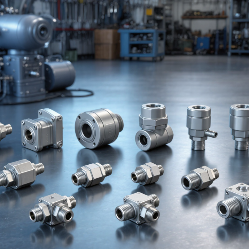
Hydraulic couplers may look alike, but their interfaces are not automatically interchangeable. ISO 7241 defines dimensions and performance requirements for quick-action couplings, including Series A and Series B. Series A and B use different interface designs, so a matching nominal size alone does not confirm compatibility. Not every coupling fits. Check the series, size, and applicable specification before connecting equipment.
In practical use, Series A is often selected for agricultural and mobile machinery, while Series B is common in industrial systems. These are typical applications, not strict rules. Both series can have different pressure ratings, seal materials, and flow capacities. A coupling that connects may still restrict flow or exceed its safe working pressure. Inspect the mating faces, confirm the equipment’s pressure limits, and check for leakage after connection. Standards help, but real-world wear and manufacturing tolerances deserve attention.
Tips: Compare the complete coupling specification, not just its outside diameter. Keep dust caps clean, and replace damaged seals. Never force mismatched halves together. If the system operates under pressure, follow its approved connection procedure; guessing here is not worth the risk.

A qualitative comparison of common coupler families. The index describes typical design intent, not measured leakage or a product performance rating.
How to read: 1 = conventional connection with limited spill-control focus; 2 = some spill-reduction features; 3 = designed to minimize fluid loss during connection or disconnection. Flat-face and dry-break designs generally emphasize fluid-loss reduction. Actual results depend on the specific coupling, operating conditions, and maintenance. ISO 7241 defines Series A and Series B as distinct series; matching nominal size alone does not make them interchangeable.
Hydraulic couplers are best compared by how they connect and control fluid, not by name alone. Threaded couplers tighten with a rotating sleeve, while push-to-connect designs engage with a direct push. Screw-to-connect couplers use threaded engagement for demanding service. Ball-lock couplers secure through internal locking balls. ISO 7241-A and ISO 7241-B refer to different interchange profiles, so verify dimensions before pairing components. Fit matters.
Valve design adds another layer. Poppet couplers use spring-loaded valves that close when disconnected; flat-face couplers reduce trapped fluid and make exposed surfaces easier to wipe. Single-shutoff designs close one side, while double-shutoff designs close both sides. These categories can overlap: a flat-face coupler may also have double shutoff. This taxonomy is useful, but not perfectly tidy. A field check should include pressure rating, flow needs, hose size, residual pressure, and contamination exposure. For example, a dusty loader connection needs clean mating faces and a secure lock, not just a familiar profile. Ratings and interchangeability depend on the exact assembly. Don’t assume a similar-looking coupler will fit safely.
A practical comparison of common hydraulic quick couplers and related connection types, including their mating method, valve design, typical applications, and buyer considerations.
| No. | Coupler Type | Connection / Locking Design | Valve / Shutoff Design | Typical Uses | Buyer Considerations | Common Standard or Reference |
|---|---|---|---|---|---|---|
| 1 | ISO 7241 Series A | Push-to-connect mating halves, commonly retained by locking balls and a sliding sleeve. | Typically spring-loaded poppet valves in both halves; valves open when the couplers are connected. | General-purpose hydraulic circuits in mobile equipment, agriculture, and industrial machinery. | Confirm the series, size, pressure rating, seal material, and dimensional compatibility; appearance alone does not establish interchangeability. | ISO 7241-1, Series A |
| 2 | ISO 7241 Series B | Push-to-connect design with a locking sleeve and ball-lock retention on many configurations. | Commonly uses spring-loaded poppet shutoff valves. | General-purpose industrial and mobile hydraulic connections, including applications where Series B dimensions are specified. | Series A and Series B are different dimensional series; verify the required series rather than relying on nominal size alone. | ISO 7241-1, Series B |
| 3 | ISO 16028 Flat-Face | Push-to-connect coupling with flat mating faces and a sleeve or locking mechanism. | Flat-face valve elements close when disconnected, helping limit fluid loss and contamination entry. | Construction and mobile equipment, where clean connection and reduced spillage are important. | Check pressure, flow capacity, face cleanliness, and whether the specific design permits connection with residual pressure. Many designs require pressure relief before reconnection. | ISO 16028 |
| 4 | Agricultural Quick Coupler | Commonly a push-to-connect design used for tractor and implement circuits; exact retention details depend on the configuration. | Often uses poppet-style shutoff valves; valve and sleeve designs vary by product. | Tractor remote hydraulics and agricultural implements. | Check the specified agricultural interface, size, working pressure, and compatibility with the tractor’s existing coupler. Do not assume all agricultural couplers share the same dimensions. | ISO 5675 for applicable agricultural couplings |
| 5 | Screw-to-Connect Coupler | Mating halves are joined and secured by rotating a threaded sleeve or coupling nut. | Often uses poppet shutoff valves; valve details depend on the design. | Hydraulic systems needing a securely retained connection, including some higher-pressure or vibration-prone applications. | Verify thread form, pressure rating, tightening procedure, and whether the coupler is designed for connection under residual pressure. Never assume these features from the connection style alone. | ISO 14540 covers certain screw-to-connect hydraulic couplings |
| 6 | Push-to-Connect Ball-Lock Coupler | The plug is pushed into the socket; locking balls engage a groove and are held by a sleeve. | May use poppet valves or other shutoff arrangements, depending on the coupler series. | Frequently connected and disconnected hydraulic lines where a quick, tool-free connection is required. | “Push-to-connect” describes the mating action, not a universal size or standard. Confirm the exact profile, pressure rating, and interchangeability requirements. | Design-dependent; confirm the specified series or dimensional standard |
| 7 | Push-Pull Coupler | Designed so connection or disconnection can be carried out by pushing or pulling the hose or implement connection, subject to the product design. | Usually incorporates automatic shutoff valves in the mating halves. | Tractor and implement connections where operators benefit from straightforward coupling and uncoupling. | Operating method and permissible side load vary. Check the manufacturer’s instructions, mounting arrangement, pressure rating, and compatibility with the mating half. | Application- and design-dependent; not one universal dimensional series |
| 8 | Ball-Valve Coupler | Connection may use a threaded, lever-operated, or quick-coupling arrangement, depending on the assembly. | A rotating ball with a flow passage opens or blocks the hydraulic path. | Hydraulic isolation points and selected fluid-power connections where a positive manual shutoff is needed. | Check the flow direction, pressure and temperature limits, sealing materials, and whether the design is intended for frequent quick connection. Ball-valve design does not by itself define coupler interchangeability. | Design-dependent; verify the applicable component specification |
| 9 | Dry-Break / Non-Spill Coupler | Often uses a flat-face mating interface; connection and locking method vary by design. | Shutoff elements are designed to minimize fluid loss when the halves are disconnected. | Applications where leakage, fluid handling, or contamination control needs to be reduced. | “Non-spill” describes a performance aim, not a guarantee of zero leakage. Review the rated leakage performance and pressure-relief requirements for the selected model. | Flat-face designs may use ISO 16028 dimensions; confirm the specific specification |
| 10 | Diagnostic Test-Point Coupling | A small test connection accepts a compatible pressure-test probe or measuring adapter rather than serving as a main-flow line coupling. | Typically self-sealing when the probe is removed. | Pressure measurement, troubleshooting, and condition monitoring in hydraulic systems. | Match the test point to the intended probe, pressure range, and fluid. These fittings are for measurement access, not for connecting a full-flow hydraulic circuit. | ISO 15171-1 for applicable hydraulic test-point connections |
Note: These categories are not all mutually exclusive. A coupler can, for example, be both flat-face and dry-break, or use a push-to-connect mechanism with poppet valves. Always confirm the specified dimensions, working pressure, flow capacity, fluid compatibility, and connection standard before selecting or interchanging couplers.
Hydraulic couplers may look similar on a parts shelf, but their pressure and flow ratings can differ sharply. Compare manufacturer data in bar and L/min, not just nominal size. A coupler rated for 250 bar is not automatically suitable for every circuit operating near that pressure. Check whether the published figure is a working-pressure rating, a peak value, or a test limit. Small labels matter.
Flow data needs equal care. A listing of 60 L/min means little without knowing the pressure drop measured across the coupler. A restrictive connection can heat oil and slow an actuator, even when its pressure rating looks ample. Compare ratings at similar test conditions, and check both halves of the connection. Flat-face, screw-to-connect, and push-pull designs may behave differently under the same flow demand. Look for the specified fluid, temperature range, and connection size, too.
In practice, I would match the coupler to the machine’s normal operating range, then leave a sensible margin for pressure spikes. Not guesswork. A data sheet may omit the exact pressure-drop curve, or use unclear test conditions; ask the supplier before comparing numbers. Record the figures side by side, including bar, L/min, and stated test conditions. A tidy table helps, though it cannot fix incomplete data.
For global buyers, ISO 16028 flat-face couplers and ISO 5675 agricultural couplers serve different connection needs. ISO 16028 couplers have flush mating faces that help limit fluid loss and air entry during connection or disconnection. Their smooth surfaces are also easier to wipe clean before joining. That matters around dusty loaders and equipment that changes attachments throughout the day. Mud still happens.
ISO 5675 couplers are designed for agricultural hydraulic connections, where compatible dimensions help equipment and implements connect across manufacturers. A tractor may use several coupler sizes, so check each port rather than relying on appearance. Not every similar-looking plug will fit safely. Confirm the applicable standard, nominal size, working pressure, flow requirements, and any connection-under-pressure limits with the equipment documentation. Standards support interchangeability, but they do not make every system interchangeable. Keep protective caps clean, inspect seals for cuts, and replace damaged parts before leaks become a field problem. A small detail, often missed. Global compatibility is useful, though the final fit still deserves a hands-on check.
Hydraulic couplers vary in connection style and operating purpose. Common options include ISO A and ISO B, flat-face, screw-to-connect, push-pull, high-flow, dry-break, threaded, agricultural, and diagnostic couplers.
Match seal materials to the hydraulic fluid, then check the coupler’s rated pressure. The system’s weakest component sets the safe limit. Also consider pressure spikes, not just the normal gauge reading. Even a neat fit can be wrong.
Flow matters, too. An undersized passage can create pressure loss and heat, especially during continuous operation. Flat-face designs help limit fluid loss and dirt entry during connection. Screw-to-connect styles can resist separation under vibration.
Push-pull couplers may suit frequent tool changes, while high-flow designs support equipment needing greater throughput. Check the application, hose size, operating temperature, and connection standard together. Thread size alone does not prove compatibility.
Tips: Compare the coupler’s pressure and flow ratings with measured system conditions. Confirm fluid and seal compatibility in the supplier’s technical data. Keep mating faces clean; a small grit particle can damage a seal. Selection can still involve trade-offs. A coupler that works well on a stationary test bench may be awkward to connect in a muddy field, so check access and handling before ordering.