

Transformers rarely attract attention until a substation hums, a factory line stops, or a neighborhood loses power. Yet choosing the right design affects efficiency, reliability, safety, and cost. The Types Of Transformers are not simply a list of hardware; they reflect different jobs, voltage levels, and operating environments. Some units raise or lower voltage across transmission networks. Others supply local distribution, measure electrical quantities, or isolate sensitive equipment. The categories can overlap, which is easy to miss.
The scale of grid investment makes these distinctions increasingly practical. The International Energy Agency’s 2023 report, Electricity Grids and Secure Energy Transitions, says annual grid investment must rise to more than $600 billion by 2030 in its pathway for climate goals. That figure covers grids broadly, not transformers alone. Still, transformers are essential links within those systems. The U.S. Department of Energy’s 2022 Electric Grid Supply Chain Review also reported that distribution-transformer lead times had grown from roughly three to six months in 2019 to 12 to 30 months in 2022. Supply conditions vary, and that estimate should not be treated as a current universal guarantee.
This guide compares common transformer types, including power, distribution, instrument, isolation, and autotransformers. It also explains the practical difference between dry-type and liquid-immersed designs. A label alone is not enough. Load profile, installation location, cooling, and maintenance requirements all matter. Small details matter, too. The right choice depends on the system, not just the nameplate.
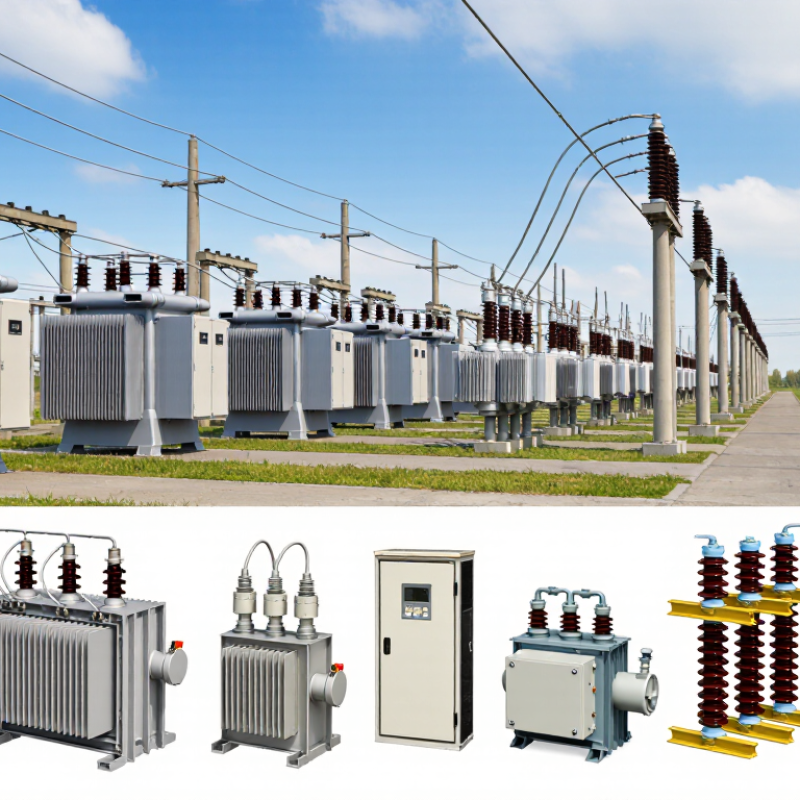
Power transformers are the workhorses of high-voltage transmission. At a generating station, a step-up transformer raises voltage so electricity can travel long distances with lower current and reduced line losses. Near cities and industrial sites, step-down units lower voltage for regional networks. Inside the tank, a laminated steel core guides magnetic flux between windings; insulating oil often carries heat to radiators. Tap changers help adjust voltage as network conditions change.
These details matter.
A transformer’s rating, insulation system, cooling method, and short-circuit strength must match its duty and site conditions. The U.S. Department of Energy’s 2022 Electric Grid Supply Chain Review reported large power transformer lead times of roughly 12–30 months, compared with 3–6 months in 2019. The International Energy Agency’s 2023 grid report says annual grid investment needs to exceed $600 billion by 2030. That wider expansion makes careful equipment planning more important, though a standard specification can still miss local constraints. Nameplate data alone is not a complete design answer; engineers also need load, fault, transport, and maintenance requirements.
Tips: Confirm voltage ratio, cooling, and site access early. Check spare-unit plans, too. A perfect specification is rare; document the trade-offs.

Distribution transformers connect local power networks to homes, shops, and small businesses. They reduce medium-voltage electricity to a level suitable for everyday use. You may see them on utility poles or inside compact ground-level enclosures. The exact design depends on network layout, expected demand, and available space. Small details matter.
On a residential street, one transformer may serve several buildings. Evening cooking, heating, and vehicle charging can raise demand at the same time. Engineers consider these patterns when selecting capacity, but real usage rarely follows a perfect forecast. That part is easy to underestimate. They also check voltage drop, protective devices, and grounding arrangements so faults can be managed safely.
Routine inspection helps keep local service dependable. Technicians may look for leaks, corrosion, unusual noise, damaged connections, or signs of overheating. In practice, records can be incomplete, and older equipment may not match current load patterns. Forecasts deserve regular review. Clear access around an enclosure also helps crews work safely and respond faster when repairs are needed.
| Transformer Type | Typical Installation | Common Capacity Range | Typical Network Role | Key Characteristics |
|---|---|---|---|---|
| Pole-Mounted Single-Phase | Overhead distribution poles | About 5–167 kVA | Supplies individual homes, farms, and small loads from overhead lines | Compact, outdoor, liquid-filled units are common. Capacity and voltage depend on local utility standards. |
| Pole-Mounted Three-Phase | Overhead poles or pole platforms | Commonly tens to several hundred kVA | Serves small commercial, agricultural, or other three-phase loads | May use one three-phase unit or a bank of three single-phase units, depending on network design. |
| Pad-Mounted Single-Phase | Ground-level, locked enclosure on a concrete pad | Often tens to a few hundred kVA | Feeds local underground residential or small commercial networks | Enclosed construction supports placement in accessible outdoor areas where overhead equipment is not used. |
| Pad-Mounted Three-Phase | Ground-level pad in a fenced or public utility area | Commonly about 75–2,500 kVA | Supplies commercial buildings, apartment developments, and local distribution circuits | Typically includes compartmentalized high- and low-voltage connections; exact ratings vary by design and jurisdiction. |
| Underground Network Transformer | Below-grade vault or dedicated indoor vault | Often several hundred kVA to a few MVA | Supports interconnected underground networks in dense urban areas | Designed for vault installation and network operation; ventilation, drainage, and access are important site considerations. |
| Dry-Type Distribution Transformer | Indoor electrical rooms, commercial buildings, or industrial facilities | Commonly tens of kVA to several MVA | Steps distribution voltage down for building or facility loads | Uses air or another gas rather than liquid for insulation and cooling. Often selected for indoor installations where fire and spill considerations matter. |
| Liquid-Filled Distribution Transformer | Outdoor poles, pads, or utility substations | From a few kVA to several MVA | Provides efficient voltage transformation across local distribution networks | Uses insulating liquid for dielectric strength and cooling. The liquid type, containment, and environmental requirements depend on the installation. |
Capacity ranges are indicative examples, not universal limits. Available primary and secondary voltages, ratings, cooling methods, and installation requirements vary by country, utility, and application.
Instrument transformers make high-voltage systems measurable and protectable. Current transformers (CTs) scale line current into a relay- or meter-friendly signal. Voltage transformers (VTs) reduce system voltage for the same purpose. Their readings help operators track load, detect faults, and isolate equipment selectively. The hardware is compact; the consequences are not. A CT that saturates during a fault can distort the signal a protection relay receives.
Network growth makes dependable measurement more important. The U.S. Department of Energy’s 2023 National Transmission Needs Study estimates that transmission capacity may need to grow 57% by 2035, compared with 2020 levels, under its moderate scenario. NERC’s 2024 Long-Term Reliability Assessment forecasts North American summer peak demand rising by 132 GW over ten years. These projections do not specify instrument-transformer demand, but they point to more equipment and operating conditions that measurement systems must handle.
Selection requires more than matching a ratio. Engineers check accuracy class, burden, insulation level, and expected fault current against the application. A common blind spot is treating the nameplate as the whole story. It isn’t. CT secondary circuits must not be left open while energized, and relay performance depends on the complete measurement chain, including wiring and settings. Site conditions matter, too; a technically correct choice can still disappoint when installation details are overlooked.
An isolation transformer transfers power through magnetic coupling while keeping its primary and secondary circuits electrically separate. In a workshop, that can help limit unwanted conductive paths between sensitive equipment and the supply. A typical 1:1 unit changes voltage very little; it does not automatically make an installation safe. Grounding, overcurrent protection, and correct installation still matter. That matters.
The U.S. Department of Energy’s 2016 distribution-transformer rule analysis projected 3.6 quadrillion Btu in energy savings over 30 years. The International Energy Agency’s 2023 grid report says annual grid investment must exceed $600 billion by 2030.
These figures describe broader transformer and grid needs, not isolation-transformer performance specifically. They offer context, not a direct efficiency claim.
In practice, check the load’s voltage, current, and frequency, then consider leakage current and any electrostatic shield requirement. A unit that is too small may overheat under sustained load.
One detail is easy to miss: isolation does not remove every shock hazard, especially when the secondary circuit is touched in the wrong way. Sizing and protection deserve a careful review. I would not assume a quieter device is a safer one.
Autotransformers for Compact Voltage Conversion
An autotransformer uses one continuous winding, with a portion shared by both the input and output circuits. This design can make it lighter and smaller than a comparable two-winding transformer. Less copper. Less cabinet space. For example, a unit converting 230 volts to 115 volts may suit equipment designed for the lower supply voltage. The exact rating depends on the load, operating conditions, and required voltage range.
That compactness comes with an important trade-off: an autotransformer does not provide electrical isolation between input and output. It may be appropriate for voltage adjustment where isolation is not required, but it is not a substitute for an isolation transformer. Check the nameplate rating, expected load current, and installation environment before selecting one. A motor starting under load, for instance, can draw considerably more current than its running rating suggests. This detail is easy to overlook. Also consider voltage variation and heat buildup in an enclosed cabinet. Application requirements differ, so a qualified electrical professional should confirm the design and protective measures.
Autotransformers use a shared winding to step voltage up or down, making them smaller and lighter than equivalent two-winding transformers in many applications. The chart shows representative nominal voltage conversions; actual suitability depends on load, frequency, and equipment ratings.
Note: Autotransformers do not provide galvanic isolation between input and output. Use an isolation transformer when electrical separation is required.